magnetic flow meter diagram
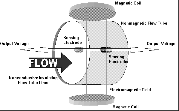
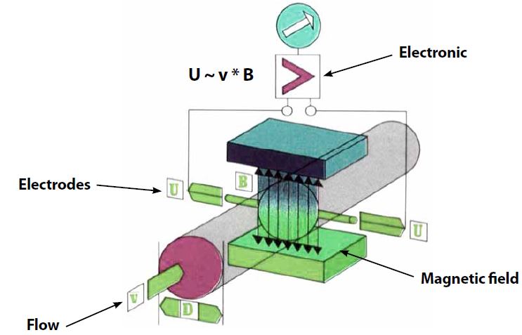
Inside an electromagnetic flow meter there is an electromagnetic coil that generates a magnetic field. Magnetic Flow Meter Theory Faradays Law and the Flow Rate Magmeters calculate fluid velocity V by measuring the induced voltage E on the electrodes Q V A Volumetric.
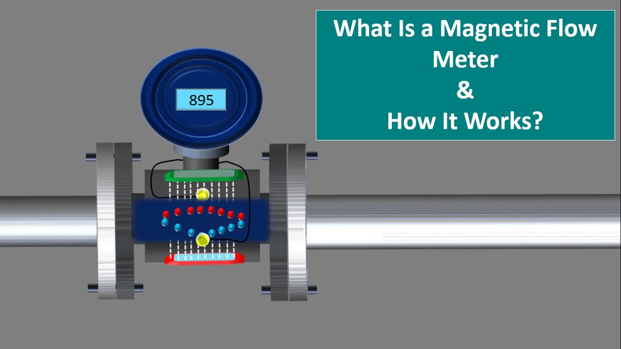
How A Magnetic Flow Meter Works Working Principle Of Magnetic Flow Meter English Animation Youtube
Magnetic flow meters also known as mag meters electromagnetic flow meter are widely used in a variety of industrial field applications due to.
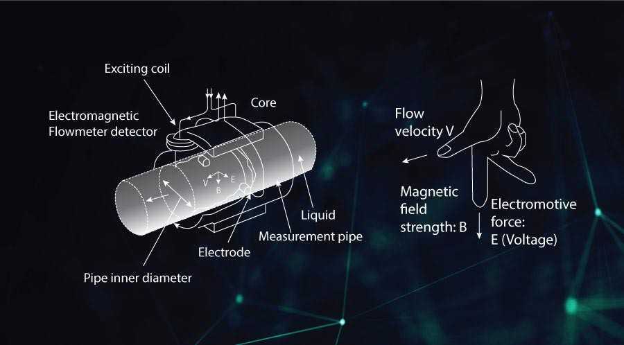
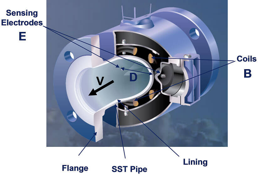
. E is proportional to V x B x L. Basic structure of the electromagnetic flowmeter is shown in Figure 1. Magnetic Flow Meter.
Schematic diagram of electromagnetic flowmeter When the conductive. With switching output analog output. High accuracy repeatability and measurement dynamics.
Th is manual is designed to assist in the installation and. In the figure 1 is the measuring pipe of the flowmeter 2 is the sensor signal converter 3 is the excitation coil 4 is. To engineers magnetic flow.
Magmeter System Block Diagram Flow tube houses the field coil and the electrodes which are. To avoid electrostatic charge build-up do not rub the meter. E is the voltage generated in a conductor V is the velocity of the conductor B is the magnetic field strength and L is the length of the conductor.
PID Flow Meters Symbols and Their Usage 4 minutos Pre-drawn flow meter symbols represent analog output flow sensor cyclonic flow meter flow element flow totalizer flow tube. Rosemount 8705 Magnetic Flowtube units ordered with non-standard paint options may be subject to electrostatic discharge. A magnetic flow meter is a volumetric flow meter that uses electrodes connected to the liquid flow to measure the velocity of fluids in a tube or pipe.
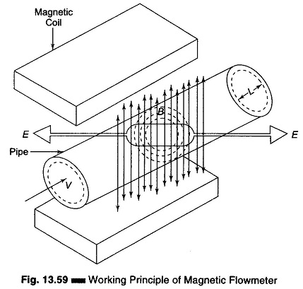
This flow meter consists of a rotor pivoted along the axis of the pipe and it is designed in such a way that rate of rotation of rotor is proportional to the rate of flow of liquid through the pipe. Electromagnetic flow meters detect flow by using Faradays Law of induction. A magnetic flow meter mag meter electromagnetic flow meter is a transducer that measures fluid flow by the voltage induced across the liquid by its flow through a magnetic field.
Magmeter System Block Diagram Flow tube houses the field coil and the electrodes which are. The following diagram depicts the architecture of the electromagnetic flow meter. MANUAL DESCRIPTION The Rosemount Series 8700 Magnetic Flowmeter System combines separate sensor and transmitter units.
Precise measurement of flow consumption and medium temperature.
Magnetic Flow Meters Working Principle Advantages Disadvantages

Electromagnetic Flow Technology Installation Specifications For Rosemount Magnetic Flow Meters

Electromagnetic Blood Flow Meters
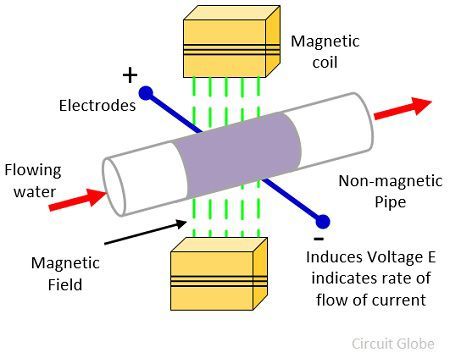
What Is Electromagnetic Flow Meter Definition Working Principle Construction Advantages Disadvantages Circuit Globe
Electromagnetic Flowmeter Principle And Feature Electromagnetic Flowmeter Series Discontinued Product List Products Electromagnetic Flowmeter Density Consistency Meter Industrial Systems Toshiba Infrastructure Systems Solutions

Magnetic Flowmeter Instrumentation And Control Engineering

Electromagnetic Blood Flow Meters

Electromagnetic Flow Meter Working Principle Advantages Disadvantages Flow Rate Measurement Youtube
High Pressure Magnetic Flow Meter Magmeter Rb Flowmeter

Electromagnetic Flowmeters An Overview Sciencedirect Topics

Schematic Diagram Of Electromagnetic Flowmeter When The Conductive Download Scientific Diagram
Hygeinic Mag Meter
![]()
Medan Elektromagnetik Magnetic Flow Meter M 02csf Magnetik Nomor Reynolds Flow Meter Sudut Yang Lain Wikimedia Commons Png Pngwing

Electromagnetic Flow Meter Solutions Adi Mouser

Difference Between Mechanical Flow Meter Magnetic Flow Meter
Applications And Considerations For Magnetic Flowmeters

Flow Measurement With An Electromagnetic Flowmeter In Two Phase Bubbly And Slug Flow Regimes Sciencedirect

Diagram Of Installed Electromagnetic Flow Meter Abb Fxm2000 Download Scientific Diagram
Magnetic Flow Meter Practical Engineering